WireViz
Summary
WireViz is a simple yet flexible markup language for documenting cables, wiring harnesses and connector pinouts with beautiful graphical output.
It is based on GraphViz and designed as an "extension" of it. A parser reads a WireViz file and generates valid GraphViz output, which can instantly be rendered to SVG/PNG.
Features
- WireViz is fully text based
- No special editor required
- Human readable
- Easy version control
- GraphViz-like syntax
- Understands and uses color abbreviations as per IEC 60757 (black=BK, red=RD, ...)
- Optionally outputs colors as abbreviation (e.g. 'YE'), full name (e.g. 'yellow') or hex value (e.g. '#ffff00'), with choice of UPPER or lower case
- Auto-generates standard wire color schemes and allows custom ones if needed
- Understands wire gauge in mm² or AWG
- Optionally auto-calculates and displays AWG equivalent when specifying mm²
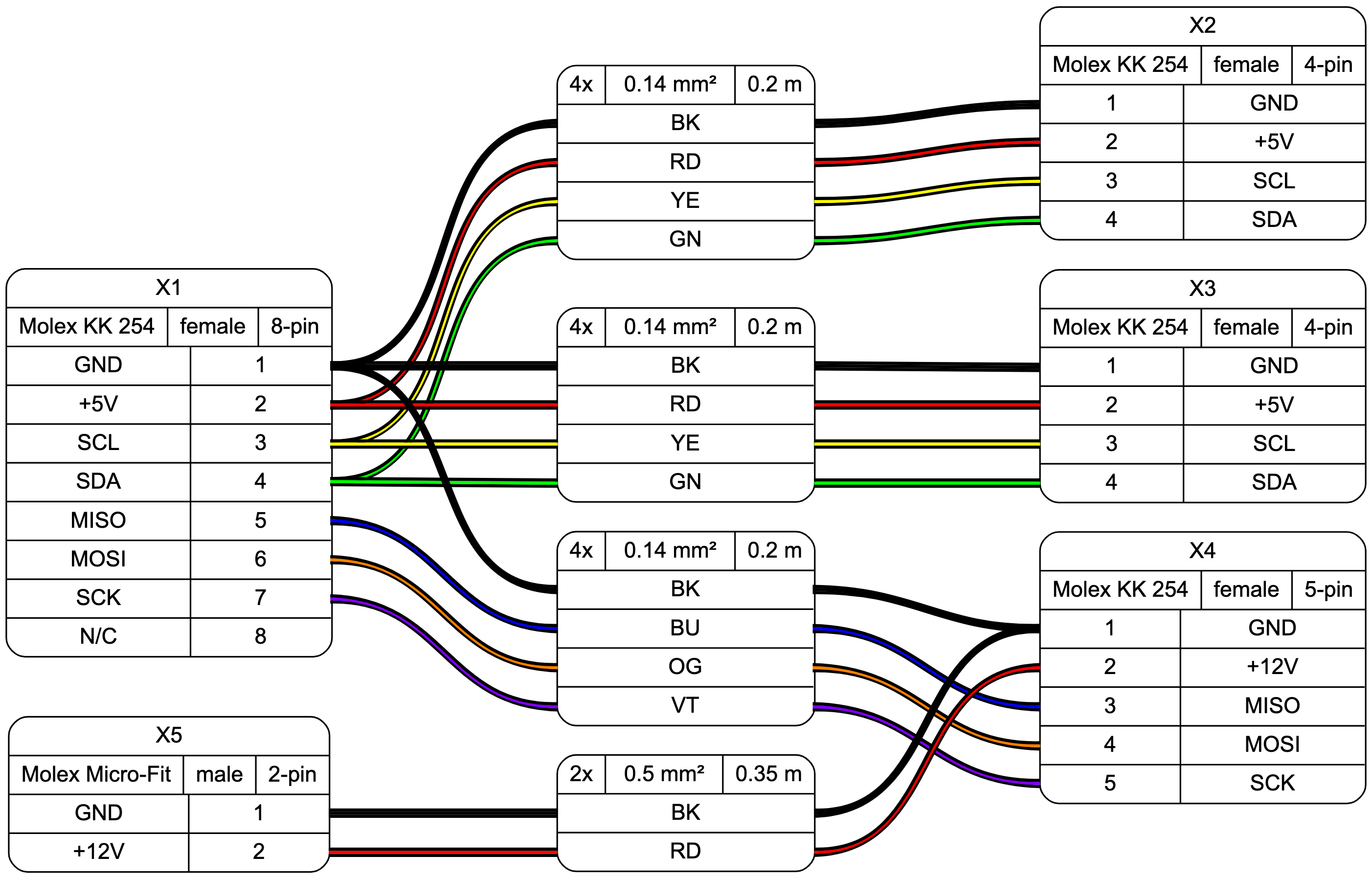
- Allows more than one connector per side, as well as loopbacks
- Allows for easy-autorouting for 1-to-1 wiring
Example
WireViz input file:
// define connectors
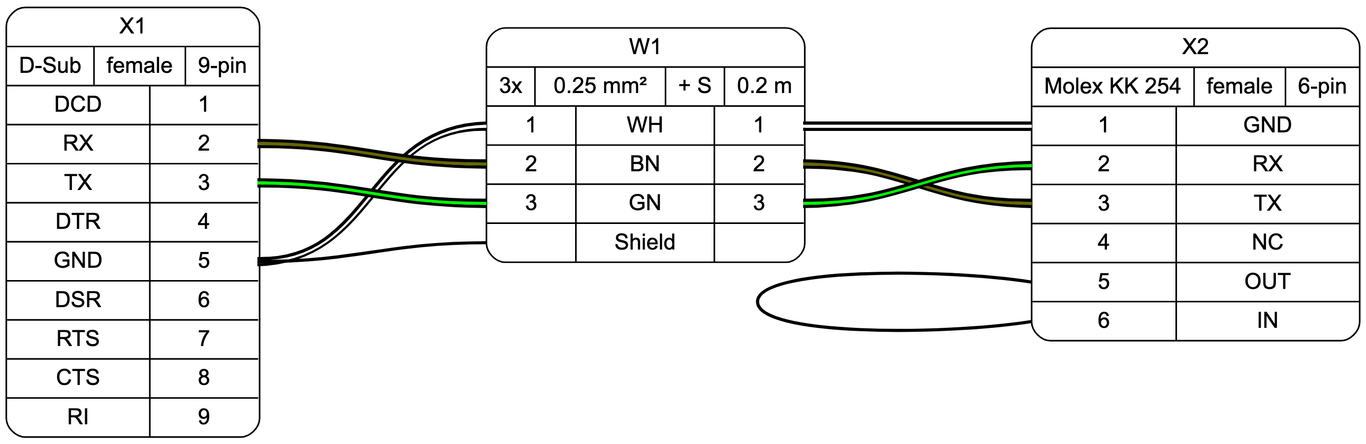
X1 [type="D-Sub",
gender="female",
pin_labels="DCD|RX|TX|DTR|GND|DSR|RTS|CTS|RI",
]
X2 [type="Molex KK 254",
gender="female",
pin_labels="GND|RX|TX|NC|OUT|IN",
]
// define wire
W1 [mm2=0.25,
length=0.2,
num_wires=3,
colors="din47100",
shield=true
]
// define connections
X1:5 -> W1:1 -> X2:1 // GND
X1:2 -> W1:2 -> X2:3 // TX-RX
X1:3 -> W1:3 -> X2:2 // RX-TX
X1:5 -> W1:S // shield
X2:5 -> X2:6 // loop
Output file:
GraphViz code generated by parser:
digraph G {
    graph [rankdir = LR, ranksep=2, fontname = "arial"];
    edge [arrowhead=none, fontname = "arial"];
    node [shape=record, style=rounded, fontname = "arial"];

X1[label="X1 | {D-Sub DE-9|female|9-pin} | {{DCD|RX|TX|DTR|GND|DSR|RTS|CTS|RI} | {<p1>1|<p2>2|<p3>3|<p4>4|<p5>5|<p6>6|<p7>7|<p8>8|<p9>9}}}"]

X2[label="X2 | {Molex KK 254|female|6-pin} | {{<p1>1|<p2>2|<p3>3|<p4>4|<p5>5|<p6>6} | {|||||}}}"]

{edge[style=bold]
X2:p5:w -> X2:p6:w
}

W1[label="W1 | {3x|0.25 mm²| + S|0.2 m} | {{<w1i>1|<w2i>2|<w3i>3|<wsi>} | {WH|BN|GN|Shield} | {<w1o>1|<w2o>2|<w3o>3|<wso>}}}"]

{edge[style=bold]
{edge[color="#000000:#ffffff:#000000"] X1:p5 -> W1:w1i; W1:w1o -> X2:p1}
{edge[color="#000000:#666600:#000000"] X1:p2 -> W1:w2i; W1:w2o -> X2:p3}
{edge[color="#000000:#00ff00:#000000"] X1:p3 -> W1:w3i; W1:w3o -> X2:p2}
{X1:p5 -> W1:wsi; }
}


}
Status
This is very much a work in progress. A Python module and test scripts are available. Running the test script will generate GraphViz output. The parser will follow later; contributions are welcome!
To do
- Automate creation of left/right side ports for connectors
- Add simple connectors (ferrules, cable lugs)
- no pinout
- graphical representation?
- Add support for cable splicing (as connector type)
- Display picture of connector underneath (including pin 1 location)
- Create parser (to make WireViz work as a GraphViz extension)
- Automatic BOM generation
License
GNU GPLv3