2.7 KiB
2.7 KiB
WireViz
Summary
WireViz is a simple yet flexible markup language for documenting wires and connector pinouts with beautiful graphical output.
It is based on GraphViz and designed as an "extension" of it. A parser reads a WireViz file and generates valid GraphViz output, which can instantly be rendered to SVG/PNG.
Features
- WireViz is fully text based
- No special editor required
- Human readable
- Easy version control
- GraphViz-like syntax
- Understands and uses color abbreviations as per IEC 60757
- Auto-generates standard wire color schemes and allows custom ones if needed
- DIN 47100 (WT/BN/GN/YE/GY/PK/BU/RD/BK/VT/...)
- IEC ??? (BN/RD/OR/YE/GN/BU/VT/GY/WT/BK/...)
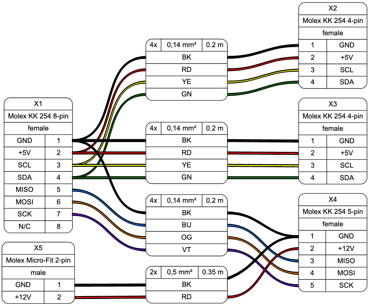
- Allows more than one connector per side, as well as loopbacks
- Will include images of known connectors, together with their pinouts
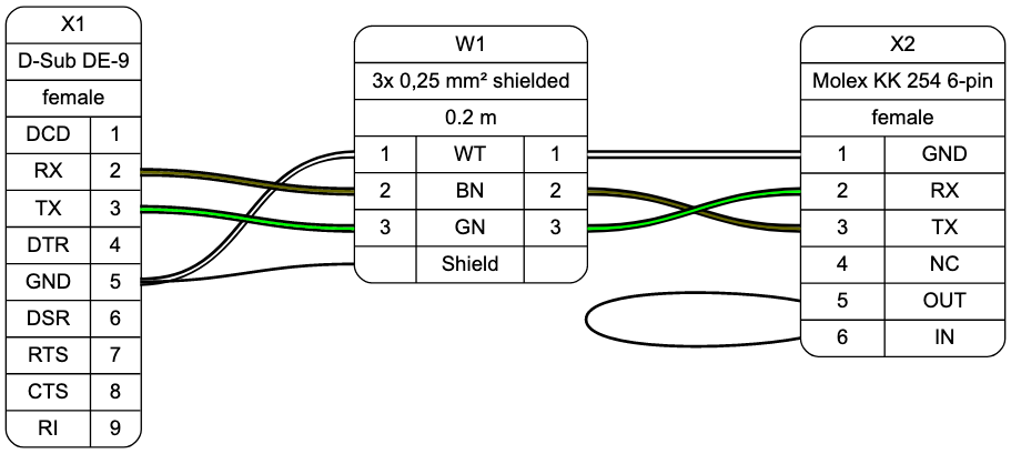
Example
WireViz input file:
// define connectors

X1 [type="D-Sub DE-9",
    subtype="female",
    num_pins=9,
    pin_labels="DCD|RX|TX|DTR|GND|DSR|RTS|CTS|RI",
    position=L
   ]

X2 [type="Molex KK 254 6-pin",
    subtype="female",
    num_pins=6,
    pin_labels="GND|RX|TX|NC|OUT|IN",
    position=R
   ]

// define wire

W1 [type="3x 0,25 mm² shielded",
    length="0.2m",
    num_wires=3,
    colors="din47100",
    shield=true
   ]

// define connections

X1:5 -> W1:1 -> X2:1  // GND
X1:2 -> W1:2 -> X2:3  // TX-RX
X1:3 -> W1:3 -> X2:2  // RX-TX
X1:5 -> W1:S          // shield
X2:5 -> X2:6          // loop
Output file:
GraphViz code generated by parser:
digraph G {
    graph [rankdir = LR, ranksep=2, fontname = "arial"];
    edge [arrowhead=none, fontname = "arial"];
    node [shape=record, style=rounded, fontname = "arial"];

    X1[label="X1 | D-Sub DE-9 | female | {{DCD|RX|TX|DTR|GND|DSR|RTS|CTS|RI} | {<p1>1|<p2>2|<p3>3|<p4>4|<p5>5|<p6>6|<p7>7|<p8>8|<p9>9}} "];
    X2[label="X2 | Molex KK 254 6-pin | female | {{<p1>1|<p2>2|<p3>3|<p4>4|<p5>5|<p6>6} | {GND|RX|TX|NC|OUT|IN}}"];

    W1[label="W1 | 3x 0,25 mm² shielded | 0.2 m | {{<w1i>1|<w2i>2|<w3i>3|<wsi>}|{WT|BN|GN|Shield}|{<w1o>1|<w2o>2|<w3o>3|<wsi>}}}"];

    {edge[style=bold]
        {edge[color="#000000:#ffffff:#000000"] X1:p5 -> W1:w1i; W1:w1o -> X2:p1; }
        {edge[color="#000000:#666600:#000000"] X1:p2 -> W1:w2i; W1:w2o -> X2:p3; }
        {edge[color="#000000:#00ff00:#000000"] X1:p3 -> W1:w3i; W1:w3o -> X2:p2; }
        X1:p5 -> W1:wsi;
        X2:p5:w -> X2:p6:w;
    }
}
Status
This is very much a work in progress, and mainly an idea in my head.