Force-add binary diagram renders that were excluded by global gitignore.
These are referenced by README.md for visual documentation.
spice2wireviz
Convert LTspice SPICE netlists to WireViz wiring diagrams.
What it does
spice2wireviz reads SPICE netlist files (.net, .cir, .sp) and LTspice schematics (.asc) and generates WireViz YAML that documents the physical wiring: connectors, test points, and inter-module cables.
Two operating modes:
- Single module -- External interface of one subcircuit (its connectors, test points, port interface)
- Inter-module -- How multiple subcircuits/boards connect to each other
It also produces Bill of Materials output as CSV, and includes layout optimization to minimize cable crossings in rendered diagrams.
Install
uv tool install spice2wireviz
# or
pip install spice2wireviz
For .asc file metadata extraction (optional):
pip install spice2wireviz[asc]
Quick start
# Inter-module wiring (auto-detected from top-level X instances)
spice2wireviz top_level.net -o wiring.yml

# Single module external interface
spice2wireviz design.net -s amplifier_board -o amp.yml

# Render to SVG/PNG/HTML (requires WireViz installed)
spice2wireviz design.net -o wiring.yml --render --format sph

# Component bill of materials
spice2wireviz design.net --bom

# Wiring bill of materials (cables, wire counts, endpoints)
spice2wireviz top_level.net --bom-wiring
Rendered diagrams
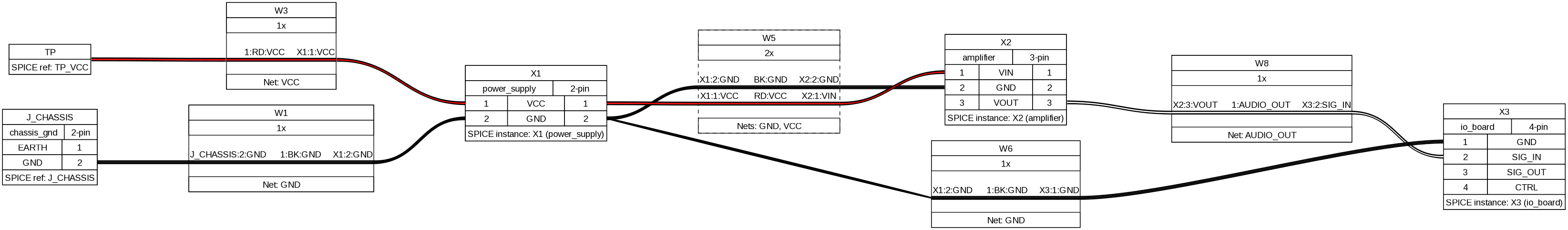
Inter-module wiring
How multiple boards/modules connect to each other — power supply, amplifier, and I/O board with shared power and signal routing:
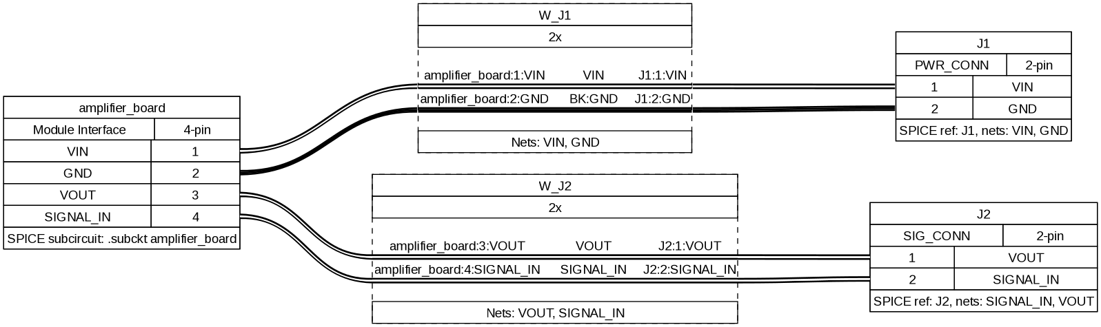
Single-module interface
External interface of one subcircuit — the amplifier board's connectors and test points radiating from a central port header:
Hierarchical system
A complex multi-level system with voltage regulator, main board, sensor module, and external connectors:
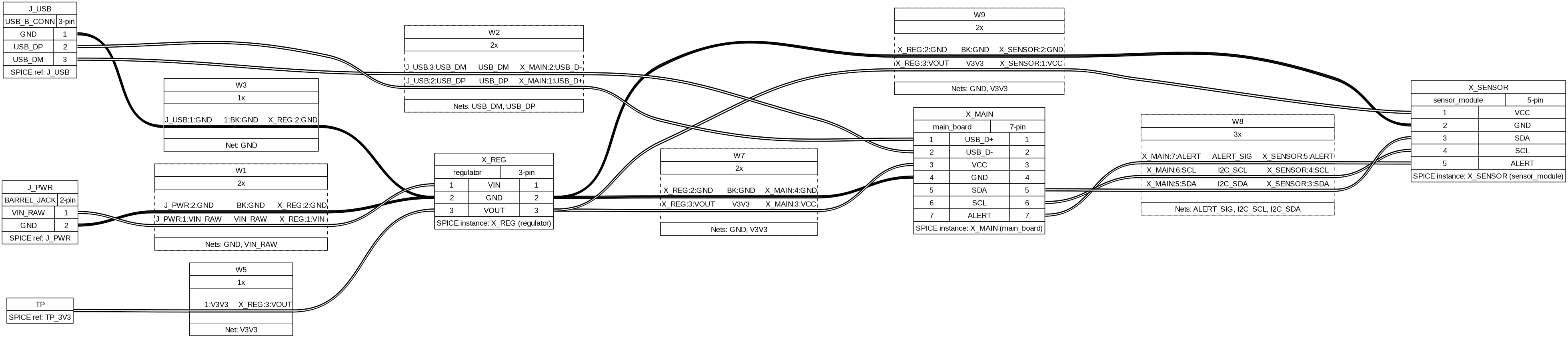
These diagrams are generated automatically by piping spice2wireviz output through WireViz (--render flag). The layout optimizer minimizes cable crossings — notice how parallel wires between the same module pair are bundled into multi-wire cables.
Output examples
Input: SPICE netlist
A multi-board system with power supply, amplifier, and I/O board:
.subckt power_supply VCC GND
J1 AC_IN AC_GND AC_INLET
.ends power_supply

.subckt amplifier VIN GND VOUT
J1 VIN GND INPUT_CONN
TP1 VOUT
.ends amplifier

.subckt io_board SIG_IN SIG_OUT GND CTRL
J1 SIG_IN SIG_OUT DB9_CONN
J2 CTRL GND CTRL_CONN
.ends io_board

* Top-level instantiation
X1 VCC GND power_supply
X2 VCC GND AUDIO_OUT amplifier
X3 AUDIO_OUT CTRL_SIG GND ENABLE io_board

* Top-level connectors
J_CHASSIS GND EARTH chassis_gnd
TP_VCC VCC
Output: Inter-module WireViz YAML
spice2wireviz multi_board.net
metadata:
  title: 'Wiring diagram: multi_board'
  source: multi_board.net
  generator: spice2wireviz 2026.2.14
connectors:
  J_CHASSIS:
    type: chassis_gnd
    pinlabels:
    - EARTH
    - GND
    notes: 'SPICE ref: J_CHASSIS'
  TP_VCC:
    type: TP
    style: simple
    pinlabels:
    - VCC
    notes: 'SPICE ref: TP_VCC'
  X1:
    type: power_supply
    pinlabels:
    - VCC
    - GND
    notes: 'SPICE instance: X1 (power_supply)'
  X2:
    type: amplifier
    pinlabels:
    - VIN
    - GND
    - VOUT
    notes: 'SPICE instance: X2 (amplifier)'
  X3:
    type: io_board
    pinlabels:
    - GND
    - SIG_IN
    - SIG_OUT
    - CTRL
    notes: 'SPICE instance: X3 (io_board)'
cables:
  W1:
    colors:
    - BK
    wirelabels:
    - GND
  W3:
    colors:
    - RD
    wirelabels:
    - VCC
  W5:
    category: bundle
    colors:
    - BK
    - RD
    wirelabels:
    - GND
    - VCC
  W8:
    wirecount: 1
    wirelabels:
    - AUDIO_OUT
connections:
- - TP_VCC: 1
  - W3: 1
  - X1: 1
- - X1: [2, 1]
  - W5: [1, 2]
  - X2: [2, 1]
- - X2: 3
  - W8: 1
  - X3: 2
Every connector includes a notes field tracing back to the original SPICE reference or instance. Ground wires are colored black (BK), power wires red (RD). Parallel wires between the same module pair are grouped into multi-wire cables (like W5 above).
Output: Single-module WireViz YAML
spice2wireviz simple_board.net -s amplifier_board
connectors:
  amplifier_board:
    type: Module Interface
    pinlabels:
    - VIN
    - GND
    - VOUT
    - SIGNAL_IN
    notes: 'SPICE subcircuit: .subckt amplifier_board'
  J1:
    type: PWR_CONN
    pinlabels:
    - VIN
    - GND
  J2:
    type: SIG_CONN
    pinlabels:
    - VOUT
    - SIGNAL_IN
  TP1:
    type: TP
    style: simple
    pinlabels:
    - N001
cables:
  W_J1:
    category: bundle
    colors: ['', BK]
    wirelabels: [VIN, GND]
  W_J2:
    category: bundle
    wirecount: 2
    wirelabels: [VOUT, SIGNAL_IN]
connections:
- - amplifier_board: [1, 2]
  - W_J1: [1, 2]
  - J1: [1, 2]
- - amplifier_board: [3, 4]
  - W_J2: [1, 2]
  - J2: [1, 2]
Single-module mode generates a central "module header" connector representing the subcircuit's port interface, with star-topology cables radiating out to each boundary component (J*, TP*, P*).
Output: Component BOM
spice2wireviz simple_board.net --bom
Reference,Prefix,Value,Pins,Subcircuit,Attributes
J1,J,PWR_CONN,2,amplifier_board,
J2,J,SIG_CONN,2,amplifier_board,
TP1,TP,,1,amplifier_board,
Component BOM lists all boundary components (connectors, test points) with their reference, value, pin count, and which subcircuit they belong to. Works even on .asc files without connectivity data.
Output: Wiring BOM
spice2wireviz multi_board.net --bom-wiring
Cable,Wirecount,Nets,From,To
W1,1,GND,J_CHASSIS,X1
W3,1,VCC,TP_VCC,X1
W5,2,"GND, VCC",X1,X2
W6,1,GND,X1,X3
W8,1,AUDIO_OUT,X2,X3
Wiring BOM lists every cable with wire count, net names, and connected endpoints. Useful for generating cut lists and wire pull schedules.
Inspection commands
Preview what's in a netlist before generating diagrams:
# List subcircuit definitions
$ spice2wireviz multi_board.net --list-subcircuits
  amplifier: ports=[VIN, GND, VOUT], boundary_components=2
  io_board: ports=[SIG_IN, SIG_OUT, GND, CTRL], boundary_components=2
  power_supply: ports=[VCC, GND], boundary_components=1

# Dry run (connector/cable/connection counts)
$ spice2wireviz multi_board.net --dry-run
Mode: inter
Connectors: 5
Cables: 5
Connection sets: 5
Connector names: J_CHASSIS, TP_VCC, X1, X2, X3
Filtering
Cherry-pick what appears in the diagram:
--include-prefixes J,TP     # Only these component types (default: J,TP,P,X)
--exclude-prefixes X        # Hide subcircuit modules
--exclude-refs X3,J_DEBUG   # Hide specific references
--include-nets "SIG_*"      # Glob patterns for net names
--exclude-nets "*_DEBUG"    # Exclude debug nets
--no-ground                 # Hide GND connections
--no-power                  # Hide VCC/VDD connections
--no-group                  # Don't bundle parallel wires into multi-wire cables
LTspice .asc support
LTspice .asc schematic files are supported with tiered netlist resolution:
- Companion netlist (automatic) -- If a
.net,.cir, or.spfile exists alongside the.asc(same basename), it's used for full connectivity. LTspice generates these automatically when you run a simulation. - LTspice generation (opt-in) -- Pass
--generate-netlistto invoke LTspice and produce a.netfile. Use--ltspice-exeto specify the LTspice binary path if it's not auto-detected. - Metadata only -- Without a netlist, only component refs/values are available. Diagram generation is blocked, but
--list-componentsand--bomstill work.
# .asc with companion .net in the same directory
spice2wireviz schematic.asc -s amplifier_board -o amp.yml

# No companion .net -- invoke LTspice to generate one
spice2wireviz schematic.asc --generate-netlist -o wiring.yml

# Specify LTspice binary path (Linux/wine, macOS, Windows)
spice2wireviz schematic.asc --generate-netlist --ltspice-exe /path/to/ltspice

# Component BOM from .asc (no .net required)
spice2wireviz schematic.asc --bom
Layout optimization
Both mappers apply layout optimization to minimize cable crossings in rendered diagrams:
- Inter-module: Sugiyama-lite layered graph drawing -- external connectors are placed at the left edge, modules are layered by BFS distance, barycenter ordering reduces crossings, and pins are reordered to group connections to the same neighbor.
- Single-module: Star topology optimization -- boundary components are ordered by their connection pattern to the module header, header pins are grouped by target component, and pin sequences are parallelized.
This is automatic and requires no configuration.
How it works
.net/.cir/.sp ─────┐
                    ├─→ Parser ─→ ParsedNetlist ─→ Filters ─→ Mapper ─→ WireViz YAML
.asc (+ companion) ┘                                    │          │
                                                         │          └─→ Wiring BOM CSV
                                                         └─→ Component BOM CSV
The parser extracts subcircuit definitions (.subckt), instances (X*), and boundary components (J*, TP*, P*) from SPICE netlists. Filters remove unwanted elements. The mapper converts the remaining structure into WireViz connector/cable/connection format. The emitter serializes to deterministic YAML (byte-identical output for identical input) or CSV.
Development
uv sync --extra dev --extra asc
uv run pytest                      # 194 tests
uv run ruff check src/ tests/
LTspice integration tests require LTspice installed and are marked:
uv run pytest -m ltspice           # Run only LTspice tests
uv run pytest -m "not ltspice"     # Skip LTspice tests (CI default)